[> ImpulsBauhaus – Interactive Table
Technical construction and method of operation
The hardware components of the interactive table
As shown in the illustration, the interactive table is comprised of two components – a beamer (A) with a projection screen (B), used for displaying contextual information, and the table itself.
One section of the tabletop (C) is comprised of a matte projection surface, on which the image from the beamer is projected. Because high-resolution beamers are not equipped with very wide-angled lenses, it was necessary to direct the projected image from the beamer (G) to the screen via a mirror (D). Although this enables the user to set up the beamer horizontally (as recommended by the manufacture), it also increases the size of the table.
The objects on the interactive table top (C) are imprinted with fiducial markers, which are simple to apply and can be easily identified by the technical components. They are visible through the projection surface from beneath and are illuminated by infrared lamps (F). The camera (H) captures the reflected image of the underside of the projection surface (C) from the mirror (D). An infrared filter blocks out the light of the projector, allowing only the infrared light from the lamps (F) to pass through. The camera not only captures the image of the markers, but also fingertips as they come in contact with the interactive tabletop. Because of the matte surface, the fingertip is visible as a sharply defined point of light only when it is right above the surface.
The computer (J) processes the data from the camera and creates an animated version of the tabletop for the beamer (G). It then sends the current status of the table to the computer (K) that controls the second beamer (A) which projects the image onto the projection screen.
Construction of the prototype
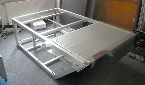
Aluminium frame construction
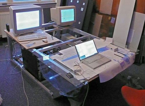
Prototype equipped with technical components
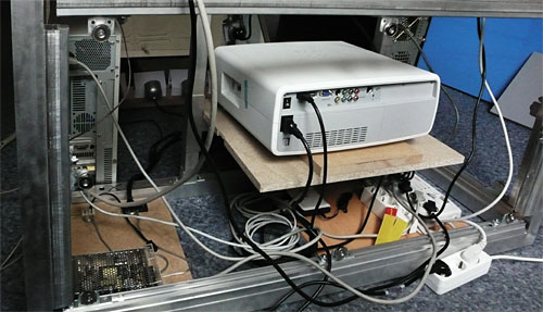
View of back: The HD beamer (centre), with light beam directed via mirror
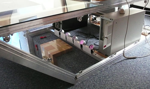
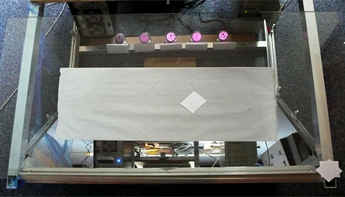
IR light emitted by five small IR lamps
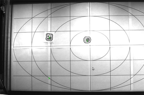
Camera image showing the calibration grid and two test markers
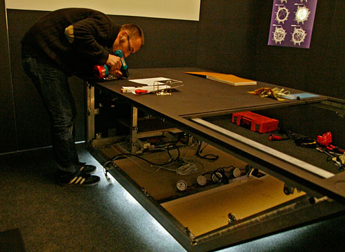
Assembling the prototype for the exhibition
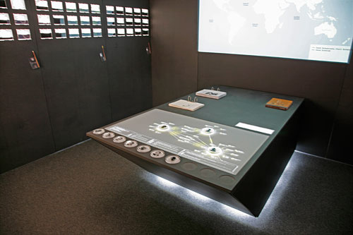
The finished exhibit on display at the ImpulsBauhaus Exhibition N°1
Technical Data:
Chassis dimension: 120 x 80 x 214 cm (BxHxT)
Display: 48" (107 x 61cm)
Aspect Ratio: 16:9
Resolution: 1920×1080 Full-HD
Brightness: 1200 ANSI Lumen
Display Technology: LCD
Contrast: 10000:1
Tracking-Frequency: ~40 Hz
Tracking-Resolution: 1024×720
Audio: integrated speakers and mini amplifier
Interface: on/off via remote control
Recognition Software: ReacTIVision-1.4
Power consumption: Less than 800W
Ventilation: integrated
Software architecture
The interplay between hardware and software
To describe how the unit works, we begin with the camera. It takes an infrared image of the tabletop which is then analysed by the reacTIVision module in computer A.
reacTIVision is a reliable open-source framework for image processing. It is specially designed to quickly recognize fiducial markers and process multi-touch events. Instead of processing camera images one at a time, the status of the table is saved to memory, which allows the system to recognize events, such as finger movements, rotating markers and other changes. Using a TUIO protocol, it sends these interactions to the processing module where it interprets the event. For example, it recognizes when a new marker has been placed on the table and generates acoustic and visual feedback via the beamer and loudspeaker. In order to give the user a feeling of smooth, intuitive motion, it is very important to generate an immediate response to the user’s actions. Consequently, the chain of hardware components should have as low latency as possible.
Every marker has a distinctive ID and can be assigned to each person. The software requests relevant information from a web service on the research platform. It can directly access the ImpulsBauhaus database via Internet, but most often uses a local copy. This option shortens the response times and does not require a running, stable Internet connection.
Computer B is used to project additional geographic information outside the table environment onto the screen. The Flex application, running in the background, receives information about the status of the table from the processing module and then offers its own map service by independently obtaining data from the research platform. If connected to the Internet, it can also access maps from online services, such as GoogleMaps or Yahoo!Maps.
Computer B also monitors the unit, generates error messages and can reboot services if necessary.
The computers A and B were only separated to enhance system stability and performance.
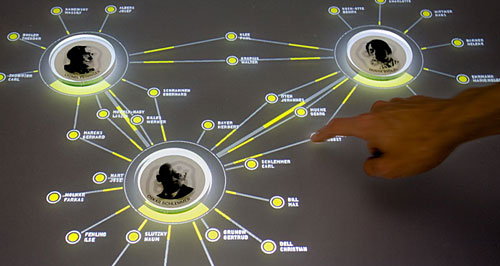
An interface to research the social network of the Bauhaus movement
Video: http://vimeo.com/5152418
[> Website: http://impuls-bauhaus.de
[> More Photos from the Exhibition N°1
Project by
Jens Weber
Andreas Wolter